- FEATURES
- PERFORMANCE
Features
◼ High respond
◼ Low hysteresis
◼ Integrated pressure compensator in channel P
◼ LS pressure limit valve for A and B
◼ Shock/suction valves for A and B ports
◼ Up to 10 basic modules per valve group
Applications
◼ Warehousing Logistics
◼ Aerial Platform
◼ Engineering Machinery
◼ Agriculture Equipment
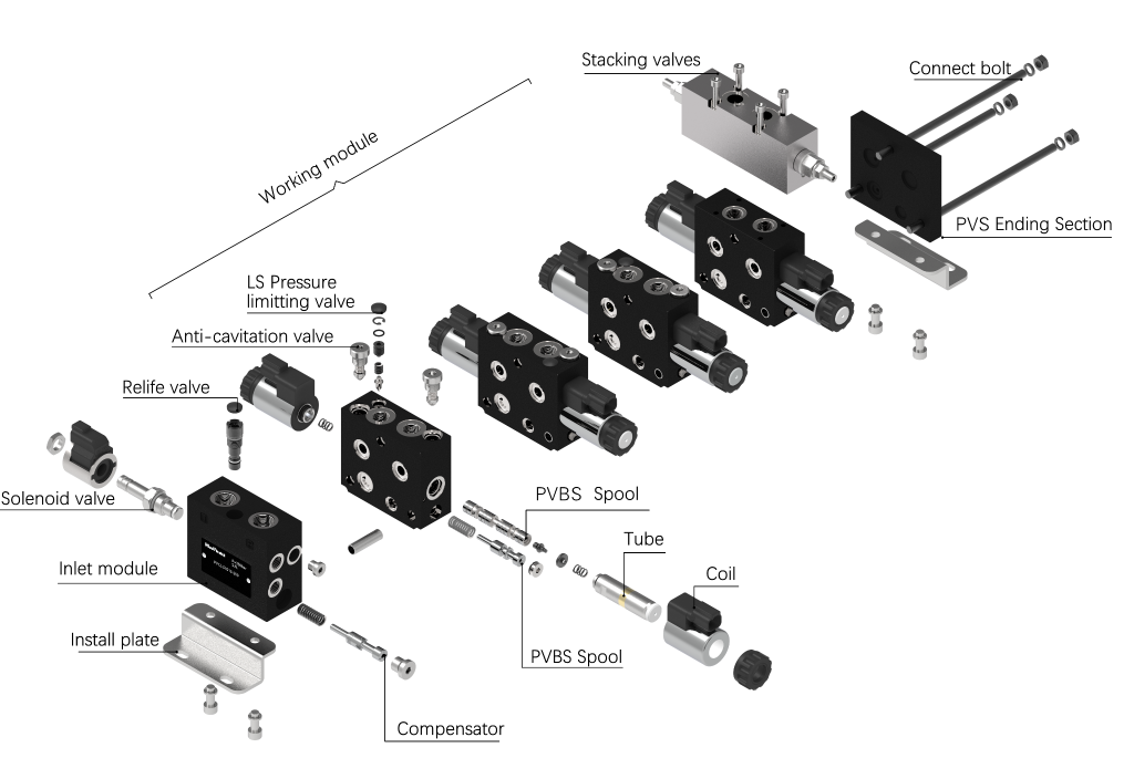
Modules
Functional description
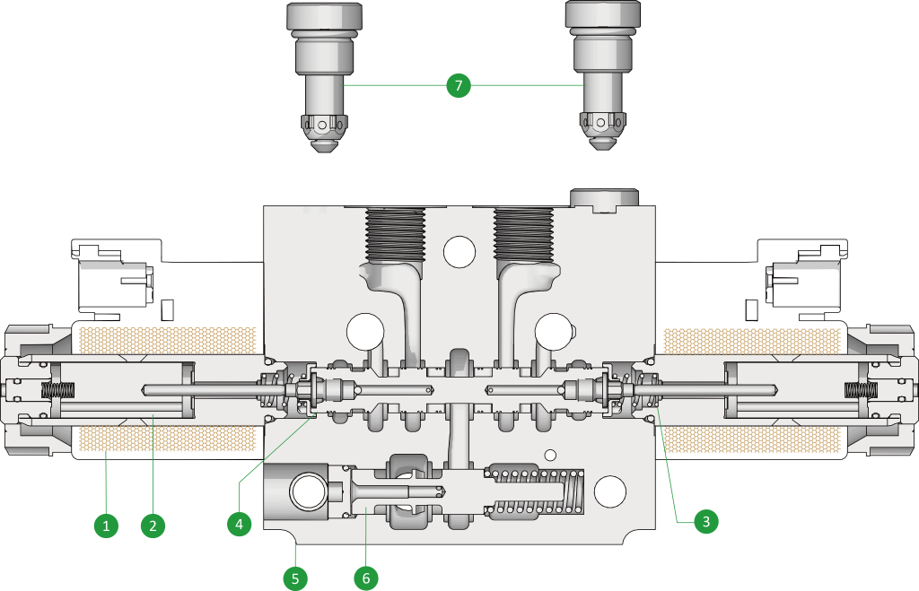
①Coil ②Armature ③Spring ④Spool ⑤Housing ⑥Compensator ⑦Anti-cavitation valve
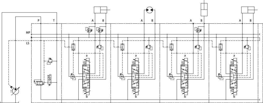
The PV12 direct-drive load sensing proportional valve is used to control hydraulic actuators. The working section modules is mainly composed of housing, spool, electromagnetic drive part, compensator and pressure limiting valve. When the solenoid coil (1) is deenergized, the spool is in the middle position under the action of the return spring (3); when one side of the coil is energized, the coil generates a magnetic field so that the armature (2) generates mechanical force, overcomes the spring force (3) and pushes the valve core (4) to slide in the valve body (5), the oil begins to throttle through P->A/B, T->B/A, and the flow area is proportional to the current obtained by the coil; when the coil is powered off, the valve core recovers the center position under the action of the return spring (3). The pressure compensator (6) is used to maintain differential pressure of the spool (4), so that the proportional valve is controlled not to be affected by the load, and the output flow rate is kept constant. The pressure of each working section is connected to the LS oil port through the shuttle valve between the working sections, and this signal can be fed back to the variable pump to control the maximum pressure. Anti-cavitation valve (7) can prevent the pressure of A or B from being overloaded or suctioned. LS relief valves can be set according to the needs of different applications.
Technical data
General | ||||
Series | 12 | |||
Weight | Inlet modules | 2.9kg | ||
Work modules | Single coil | 2.7kg | ||
Double coil | 3kg | |||
Outlet sections | 0.1kg | |||
Working Oil | Mineral hydraulic oil HL/HLP | |||
Working Temperature | -30~100℃(NBR) | |||
Working viscosity | 20~380 mm²/s | |||
Filtration | ISO4406: 20/18/15 | |||
Hydraulic data | ||||
A/B/P Max. Pressure | 350 bar | |||
T Max. Pressure | 210 bar | |||
Rated Flow(ΔP=6bar) | 40 L/min | |||
Y Schema A/B→T flow area | 2% | |||
Electrical data | ||||
Voltage | 12V DC | 24 V DC | ||
Current | 1.76 A | 0.94 A | ||
Resistance | 4.05 Ω | 13.6 Ω | ||
Voltage ripples | ±10% | |||
Duty | 100%(Ambient temperature≤50℃) | |||
The maximum temperature of the coil | 180℃ | |||
Insulation | H | |||
Coil Weight | 0.23 kg | |||
Application example